Showing posts with label Solar. Show all posts

Wednesday, 6 June 2018

Powerwall 2 Time Base Control Algorithm

Since PW2 (Tesla Powerwall 2) introduced the new TBC (Time Base Control) algorithm, I had a great difficulty in trying to understand the actual algorithm, especially during shoulder period. Consulting forum (such as here and here) only confuses me further, especially when the forum started to discuss incentives and local regulations (US centric). This, however, makes me appreciate the herculean task for PW2 engineers. You simply can't make everyone happy.

The ever evolving nature of PW2 algorithm (typical Tesla my guess), makes any 'User Manual' writing attempt a futile exercise. Reverse engineering the algorithm also requires different permutation, such as state of charge, how much PV production during the day, etc that can affect the PW2 behaviour.

Still, little documentation is better than nothing. Since I don't have the stamina to try all permutations, I deliberately write down as much details below (trying to be as neutral as possible, i.e. no incentive and regulation jargon):

Off-Peak Cost Saving Mode:
In this mode, PW2 does try to aim a certain State of Charge prior entering shoulder and peak period (by charging from the grid if necessary). Based on the limited 2 days experiment (see screenshot below), this State of Charge (SoC) is not a fixed value. How does PW2 decides this SoC level? Me no idea.


Also, some charge from PW2 is used during off-peak period (see bubble number 1 in the screenshot). I don't know how PW2 decides when to use the battery. One thing for sure: it mostly uses the grid to conserve the SoC for peak period.

I haven't tested what happens when you have solar production during off-peak period.

Shoulder Cost Saving Mode:
Now this gets interesting. In day 1 of the test (see bubble number 2), my PW2 behaved as I wanted it, that is: no grid activity (i.e. to behave exactly like peak). Too bad I didn't record the SoC, but I remembered it was roughly 40-ish percent at this stage.

In day 2 (see bubble number 3), my PW2 started to be less agressive (despite higher SoC compared to the previous day), i.e. grid activity is allowed by importing and exporting. Uh oh, for me, who has a power provider that value exported PV close to zero (yup, zilch, nada), this is bad news. Also, why PW2 allows a significant grid import when the battery SoC is relatively high (roughly 60-ish percent at bubble number 3). Is this because PW2 hasn't learnt that I don't usually use lots during peak period? My guess at this stage, this is due to the PW2 algorithm is based on US-centric market, where they have incentive to export PV to the grid (such as net metering). Pure guess though.

At this stage, my panic mode was on, and I switched it back to 'Self-powered' mode (as commented by the red line), which explains why the screenshot is no longer showing peak/off-peak on the 14-th May, and also 100-ish watt grid consumption during solar production after the switch (see my previous post).

After 14th of May, I changed PW2 to 'TBC Balanced' mode and extended the peak period to also cover shoulder (i.e. only peak and off-peak, no shoulder). This has worked perfectly for me, but...

In the last 2 days, I haven't had enough PV production to cover my shoulder and peak. This has caused me grief since now I need to import from the grid during peak period (see bubble number 4). So, I changed it to TBC 'Cost Saving' mode, thinking that PW2 would've charged from the grid during off-peak to cover my PV production shortfalls. To my surprise, it didn't (although the SoC was just a tad below under reserve).

So, here I am, finding another quirk in PW2 algorithm. If you don't set the shoulder period,  PW2 will not charge from the grid (despite the PW2 SoC at the reserve level). What the??

In the screenshot below (see bubble number 5), you can see that as soon as I bring back the shoulder period, PW2 behaves as I expected again by start charging from off-peak grid (I've found this by coincidence).

In short, for those who want exporting to the grid at the very lowest priority, I recommend to use 'TBC Cost Saving' mode with a wee bit of shoulder period (just enough to activate 'charge from off-peak grid mode').


PS: Peak period behaviour is consistent as expected, i.e. no import from the grid.

Monday, 13 November 2017

My Observation of Tesla PowerWall2

My Tesla Powerwal 2 (PW2) summary, freshly installed just 3 days ago:
[UPDATED 7 May 2018: see point 6 below]
  1. PW2 can be installed in multiphase (mine is 3-phase). PW2 monitors each phase current using Current Transformer (installed by the installer of course).
  2. PW2 basically absorbs all your solar power instead of injecting them back to the grid. What is worth to be noted, although you have load on different phases, the PW2 will compensate this so that your electricity meter reads export as 'zero' (since Australian domestic electricity meters don't care on which phase you're consuming). So, in my example, I was using an induction stove top at 1000 Watts on the 'white' phase, and the PW2 injecting back to the grid at 1000 Watts at 'red' phase, resulting net zero export. To mention the obvious, PW2 inverter maxed out at 5kW power.
  3. Non-noticeable transfer time when the grid has failed. I've tested this 2 times: at first attempt, the solar panel inverter anti-islanding has to reset (causing the solar power to cut for about a minute). In the second attempt, the solar inverter didn't trip at all (as if nothing happen). I'm definitely impressed on this one. To mention the obvious, only 'red' phase of my home is backed up by PW2. Other phases are not. Now I can officially welcome mad max scenario!
  4. During daytime (when the solar panel is active), I've noticed PW2 constantly draws around 100 Watts from the grid, but not at night time. I can't find any info in the internet on the why, yet. My guess, PW2 requires power for its own functionality and ineffeciencies in converting AC to DC and somehow only compensates during daytime? 
  5. It is also worth to be noted, unlike the Tesla cars, users can't set the maximum charge level on PW2. My guess, Tesla is now extremely confident that this is no longer required. Maybe combination of newer chemistry and internal software to limit when required during hot days?
  6. My particular one consistently under report kWh used and exported to the grid by roughly 15 - 20% (compared to my grid provided meter). However, the solar energy kWh is spot on (compared to my soalr inverter kWh measurement). No idea the why. Anyone experiencing the same issue?


What it doesn't do and I wish Tesla will update this functionality sometimes in the future:

  • Change the timing on the 100-Watt constant draw from the grid. I wish this is user configurable. For example, to draw this at night time, or to use solar panel instead. For me who on Time of Use plan, this total of 1kWh on daytime is something I'm not willing to pay the grid for. Call me stingy.
  • Ability to charge PW2 from the grid during off-peak via the app. At the moment PW2 only absorbs power from solar panel. Since my solar panel is not enough for my usage, I'd love to have the ability to get cheaper electricity at night to be used by my household during peak time. Quicker ROI anyone?


Now, to how I use the Tesla app:

  • Once the installer enter account holder details via the installer page, your PW2 will be immediately visible on the Tesla app (you'll need wi-fi router for PW2 to connect to Internet). I haven't accessed the PW2 directly via the ethernet router (no reply). Will try again next time.
  • The visualisation of the app is indeed very useful. For a data hoarder like me, the visualisation has altered my energy usage. For example, now I know my inverter reverse cycle Air Conditioner doesn't have linear energy consumption (I thought it does). It has step changes, i.e. 2.4kW at full power, then 1.5kW, then 900 Watts at lowest power (in cooling mode). When the PW2 is low in charge, I deliberately turn off my air-con to minimise grid usage and happy with slightly higher room temperature (but still comfortable). My guess, sometime in the future, all home appliance will talk to each other (via ethernet router, just like the PW2 at the moment) and have AI (Artificial Intellegence) based on user preference on how and when to consume energy (whether to save energy, or maximum comfort).


So here is my data, just 1 day after it's being installed (grid data not shown for clarity):

Tesla PW2 App Visual


The data above is definitely not my average day. I had to travel 120-ish km on that day, so most consumption gone to EV (I'm guessing around 18kWh).

Now my debt has increased significantly again (thanks to PW2 as an expensive toy), so the family now have to be content living from boiled water and salt. At least we have a good-lookin' dead weight on the wall now (wheel added in MS Paint to make me feel less guilty by the dead weight):


[UPDATE 12 Oct 2020 for 2018 annual figure]:


Tuesday, 6 September 2016

Motor Listrik

Akhirnya, Indonesia akan memproduksi sepeda motor listrik [1]. Sedikit telat, tapi lebih baik telat daripada tidak sama sekali. Menurut saya, tidak ada yang spesial dari sepeda motor listrik ini. Modelnya hanya mencontoh dari motor bebek. Eropa, Amerika, Cina, Jepang, dan banyak negara lainnya sudah memproduksi sepeda motor listrik mereka sendiri, dan modelnya jauh lebih menarik.

Melihat spesifikasinya, produsen motor listrik ini mengunggulkan koneksi ke smartphone Android. Daripada menambah fungsi-fungsi 'nggak-penting' (untuk apa CPU ber-GHz di motor listrik??), produsen motor listrik di Indonesia, bersama dengan pemerintah (PLN), seharusnya juga memproduksi motor listrik untuk kelas 'ekonomi'. Sistem Baterai yang sama juga bisa digunakan untuk elektrifikasi daerah pedalaman yang sulit terjangkau oleh listrik.

Saat ini, banyak daerah pedalaman yang masih menggunakan gen-set untuk mendapatkan listrik. Bahan bakar untuk gen-set di daerah pedalaman, apalagi ratusan pulau di Indonesia Timur, harganya tidak terjangkau (berhubung mahalnya ongkos kirim). Walaupun beberapa daerah mendapat subsidi, anggaran tersebut seharusnya digunakan untuk kepentingan lainnya, seperti membangun infrastruktur daerah.

Stasiun-stasiun pengisian baterai (dari panel surya, atau sumber energi terbarukan lainnya) dibangun di daerah-daerah ini untuk mengisi baterai motor listrik. Bagi yang mampu, bisa memasang panel surya sendiri di rumahnya. Dengan sistem energi terbarukan, tidak perlu lagi bayar ongkos kirim untuk bahan bakar. Sampai di rumah, baterai yang sama bisa digunakan untuk lampu, TV, dan pengisian telpon genggam dan banyak lainnya. Sistem peminjaman juga harus diterapkan, karena tidak mungkin masyarakat membayar harga motor-motor listrik ini.

Baterai untuk motor listrik ini tidak dapat diremehkan. Dengan kapasitas hampir 2kWh, baterai ini bisa digunakan untuk mengoperasikan kulkas kecil beberapa hari. Sulitnya implementasi di lapangan, saat ini, karena tidak adanya standardisasi untuk tegangan rendah. PLN seharusnya mempelopori standardisasi tegangan rendah untuk daerah pedalaman. Dengan adanya standardisasi ini, produsen-produsen lokal bisa mulai memproduksi peralatan rumah tangga yang mampu menggunakan baterai yang sama dengan motor-motor listrik ini. Contoh, motor listrik ekonomi mungkin bisa menggunakan baterai 48-Volt, dan peralatan rumah tangga untuk daerah-daerah pedalaman ini (seperti lampu, kulkas, sampai kompor listrik dengan induksi) bisa menggunakan sistem ini juga.

Kalau saya sendiri saja sudah merakit sepeda listrik sendiri dan diisi ulang oleh panel surya. Masa produsen besar tidak bisa?


Sekali tepok, ratusan nyamuk. Tidak perlu konek-konek-an ke Android.

Sumber:
[1] http://www.jpnn.com/read/2016/05/05/401025/Ini-Keunggulan-Gesits-Motor-Listrik-Buatan-Indonesia-

Thursday, 8 October 2015

Proposal Elektrifikasi Pedalaman Indonesia

Pedalaman Indonesia masih banyak yang belum terjangkau oleh listrik karena infrastruktur yang masih minimal. Memasang jaringan kabel listrik ke daerah pedalaman masih sulit dan mahal.

Biasanya, daerah pedalaman menggunakan genset (generator set). Nah, menggunakan BBM untuk listrik sangat boros dan mahal. Contoh, hanya untuk penerangan dan mengisi ulang baterai, penduduk ini [2] menghabiskan Rp50,000 per malam . Boros bukan?

Belum lagi masalah logistik bahan bakar minyak ke daerah pedalaman. Semakin terpencil, semakin sulit untuk mendapatkan bahan bakar. Contoh, di daerah Timur Indonesia, bahan bakar saja sampai dikorupsi [3]. Waduh, sudah jatuh, tertimpa tangga pula!

Nah, kebanyakan dari kita (yang bisa akses internet dan baca) sudah tahu, bahwa panel surya jauh lebih cocok untuk elektrifikasi daerah pedalaman. Dengan tidak perlunya bahan bakar (kecuali sinar matahari), semua masalah di atas, ya teratasi!

Tapi, kenapa kita (Indonesia) masih sulit menerapkan sistem panel surya ke daerah pedalaman? Instansi pemerintah sudah banyak yang mencobanya [4], dan juga organisasi non-profit [5], dan banyak lainnya. Tapi, tetap saja masih banyak desa dan daerah pedalaman yang belum terjangkau listrik. Tanya kenapa?

Menurut saya, masalahnya bisa dikategorikan sebagai berikut:

1. Keterjangkauan Harga
Panel surya dan baterai memerlukan harga beli yang tinggi, walaupun ongkos operasional selama penggunaan hampir nol. Masalahnya, para pengguna hanya sanggup membeli dengan harga beli yang rendah, dengan harga operasional yang 'terjangkau'.

Masyarakat pada umumnya lebih memilih untuk membeli gen-set kecil seharga satu juta dengan membeli BBM seumur hidup (ongkos operasional), dibanding membeli perangkat panel surya dan baterai seharga 3 - 4 juta rupiah (walaupun tanpa biaya operasional sepeser pun).

2. Standardisasi
Melihat contoh-contoh sukses dari lapangan (seperti [4] dan [5]), masih belum ada standardisasi seperti: tegangan, baterai, dan colokan apa yang dipakai. Semuanya terserah donatur.

Dengan adanya standardisasi, harga sistem secara keseluruhan bisa menjadi lebih murah. Para supplier tidak perlu memproduksi berbagai macam colokan, satu saja cukup. Contoh: bagi yang tinggal di kota, selama punya 'colokan' listrik, tinggak 'nyolok' bukan? Nggak usah pusing-pusing mikir colokannya nggak cocok, atau tegangannya ngaco?

Semakin banyak kompetisi untuk hal yang sama, harga akan menjadi lebih murah, gampang kan?

3. Skalabilitas
Lanjut dari masalah sebelumnya, berhubung tidak adanya standardisasi, sistem panel surya yang dibagikan ke rakyat sejauh ini tidak bisa di-'upgrade'. Kalau ada pengguna yang mau menggunakan listrik lebih kuat (kulkas, mesin, dll), bagaimana sistem yang sudah ada mengatasinya?

Sejauh ini, berhubung tidak ada standardisasi, kalau mau 'upgrade', ya mesti beli sistem yang lebih besar. Sistem sebelumnya jadi sama sekali tidak bisa digunakan. Ini sebuah pemborosan dan mahal.


Proposal:
Nah, berhubung saya nggak punya duit, proposal saya hanya untuk mengatasi standardisasi, alias 'the low hanging fruit'. Yang gampang-gampang dulu aja, yaitu standardisasi.

Berhubung produk di pasaran sudah banyak yang menggunakan 12 Volt, kenapa kita tidak mulai dari standardisasi 12V? Ya, tentu saja menggunakan AC 220V lebih ideal. Tapi, siapa yang mampu memasang dan merawat peralatan 220V AC? Kita harus realistis. Berhubung belum banyak teknisi listrik di pedalaman, yang kita butuhkan adalah peralatan pembangkit listrik yang bisa langsung digunakan oleh rakyat pedalaman, dan untuk dirawat oleh mereka sendiri.

Semua colokan juga di-standardisasi, jadi kalo salah 'colok', tidak mengakibatkan konsekuensi yang drastis.

Contoh proposal:


Ilustrasi sebagian diambil dari [6].

Dengan standardisasi 'colokan' dan tegangan, pengguna di pedalaman bisa menikmati keuntungan seperti penduduk di kota. Tinggal colok! Kalo mau 'upgrade', tinggal colok panel surya dengan hubungan paralel, dan juga batre, tidak perlu beli sistem baru dari 'nol'. Proposal sistem di atas juga dirancang untuk digunakan oleh pengguna yang kurang melek listrik-listrikan. Gampang kan?

Standardisasi juga menyederhanakan sistem logistik dan penerapan di lapangan. Donatur atau supplier manapun tinggal pasang-colok (plug and play) dengan sistem yang lain. Nggak perlu pusing panel surya buatan apa, dan runcian teknis lain-lainnya.

Kunci utama standardisasi adalah '12VDC bus' [8]. Selama ini diterapkan, semuanya menjadi jauh lebih mudah. Bagi pembaca yang melek panel surya, mungkin bertanya, "Itu penerapan 'kotak elektronik' dari panel surya ke '12VDC bus' gimana?"

Naaah, ini bisa diterapkan oleh:
1. Beli produk yang sudah ada di pasaran (alias '12V charge controller')
2. Bikin sendiri (produk dalam negri). Kalo saya sendiri aja udah bisa rancang dan bikin sendiri [7], kenapa situ nggak bisa?

Dari hitungan saya, harga beli sekitar 3 juta rupiah per unit. Ini untuk panel surya 50Watt-peak (dengan elektronik), dan baterai lithium 12V 20Ah, lengkap dengan colokan. Ini cukup untuk penerangan dan isi ulang batre handphone. Berhubung memakai batre lithium, sistem ini akan tahan selama 10 tahun, alias Rp 25,000 per bulan (kredit tanpa bunga selama 10 tahun)! Murah mana, dibanding Rp 50,000 per hari untuk pemakaian BBM?

Walaupun sistem ini masih belum bisa bersaing dengan harga PLN (harga sistem ini masih sekitar Rp 5,500 per kWh selama 10 tahun, dibanding harga PLN sekitar Rp 1,500-an per kWh), kita harus realistis. Sistem ini masih jauh lebih murah (daripada genset) untuk daerah pedalaman yang belum terjangkau listrik. Lagipula, harga PLN akan terus naik selama 10 tahun ke depan.

Bagi yang kebanyakan duit, silahkan hubungi saya! Duitnya akan saya pakai untuk elektrifikasi pedalaman Indonesia. Dijamin tokcer! [1]


Referensi dan catatan:
[1] Duit nggak bisa minta balik!
[2]  http://health.kompas.com/read/2012/09/29/03513482/listrik.untuk.kaum.pedalaman
[3] http://wildlifenews.co.uk/2014/05/indonesian-cop-is-jailed-for-eight-years-for-major-timber-smuggling-racket/
[4] http://regional.kompas.com/read/2013/04/25/09085871/Pemkab.Barito.Utara.Alokasikan.300.Unit.PLTS
[5] http://id.kopernik.ngo/update/menjangkau-desa-pedalaman-bersama-mama-mia
[6] http://www.solar-electric.com/how-to-use-mc4-connectors-cables.html/
[7] http://epxhilon.blogspot.com.au/2014/06/bmppt-solar-charger-3.html
[8] 12V dipilih karena lebih banyak pilihan untuk produk konsumen yang sudah ada di pasaran, dibanding sistem 48 volt misalnya (digunakan oleh: http://news.mit.edu/2015/microgrids-rural-villages-india-0601)

Tuesday, 21 April 2015

Cheapest Commuting Challenge


What is the cheapest form of commuting [7]?

With my electric bicycle, I commute 54km round trip with 460Wh of energy, or 8.5Wh/km [1]. This energy usage is equivalent to 0.052 litres of fuel, or 0.1 litre/100km [2].

Well, hangon, surely it is cheaper to pedal with your own muscle, right? That's what I thought as well. So, being a skeptic, I did my own calculation:

Assume the rider is from Tour de France (NOT me), which can 'easily' produces 300 Watt all the time in the commute duration (to achieve the same comparison with my electric bike commuting). Let say the rider manage to output 460Wh exerted at the same time duration (1 hour and 40 minutes round trip). The rider would need 400 Calories [3]! Quick googling tells me, this is equivalent to a bigmac [4].

For food cost, this translates to $5 for a round trip. Heck, that is the same cost (fuel only) if I use my Toyota Corolla! There you go. Human powered commuting is NOT cheap [5]! (Of course, I'm ignoring the health benefit here).

My electric bike fuel cost? ... Nothing! That's right, because mine is solar powered (one way). The other way, I charge at work for free :)


"Wait a minute, you have not included your capital cost!" I hear someone complaining. Well, since I'm a cheapskate, my total electric bicycle cost is around AUD1,600. This price includes: new electric bike kit, second hand bike, second hand solar panel, and my own custom MPTT charger [6]. To date, I've clocked 11,000km and 420 cycles of charging (quite deep too) and definitely still have my 80% capacity (I haven't had the guts to test the actual remaining capacity). I predict I'll be good for at least another 400 cycles (before I need to buy a new battery), so the life-cycle cost would be AUD1,600 / 800 trips = 2 bucks a trip (or 7.5 cents per km). Try to beat that!

References:
[1] Exact value is highly dependent on wind. This figure is anywhere between 350 to 550Wh. The average speed for the whole ride is between 33 to 34km/h (not much affected by wind, almost none I say). Data source from installed Cycle Analyst on-board (http://www.ebikes.ca/product-info/cycle-analyst.html)
[2] A litre of fuel contains 8.9kWh of energy, using data from http://www.afdc.energy.gov/fuels/fuel_comparison_chart.pdf
[3] 460Wh = (460Watt)(3600seconds) = 1.656MJ = 396kcal (or 396 food Calorie, yes the Calorie unit IS confusing)
[4] Assuming 100% efficiency converting those bigmac calories to pedal energy.
[5] More reading if you don't trust me: http://www.fao.org/docrep/010/ah810e/AH810E08.htm
[6] http://epxhilon.blogspot.com.au/2014/06/bmppt-solar-charger-3.html
[7] For smart a$$ out there that says "cheapest commuting is no commuting at all, i.e. work at home!". To that, I can't top it off. Yes, I agree with you.


Thursday, 12 June 2014

BMPPT Solar Charger (3)

In pursuit improving my Boost MPPT charger, I have done the following:


  1. Update the software to use in-built PWM functionality of Arduino Uno. I've found out increasing frequency of the PWM is easy-as (simply add a line of code!!). The converter is now no longer making audible noise. Also, I get back most of the computing power of the Uno, instead of fully dedicated PWM routine. The negative of increasing PWM frequency is reduced efficiency. In my case, running 31kHz has reduced efficiency by 1%!
  2. Use MOSFET gate driver: this has increased efficiency by 2 - 3%, not bad! My inexperience made me choosing MOSFET gate driver without under-voltage lock-out, which caused the converter unstable during start-up. After much troubleshooting, I've found out the MOSFET gate driver locks the MOSFET to ON position during low voltage start-up, which cause the whole circuit short-circuited. This is now rectified by choosing another driver with under-voltage lock-out;
  3. Inductor: I've wound my own inductor using proper gapped core ETD34 core with much thicker copper wire. This has increased the current capacity and reduced EMI (so they said). However, no increased efficiency whatsoever compared to my old cowboy inductor.


I'm a bit disappointed that I haven't managed increased the efficiency significantly. I suspect my measurement method is inaccurate. As I simply read the watt reading from the el-cheapo watt-meter at the input. As the current is rippling, actual watt figure is probably different. So, next time I need to measure it properly using oscilloscope. None of the component is hot this time, so surely it's better than 90%.

New Schematic:


New software, click here. Note that the software includes my customised voltage selection during start-up. This is to accomodate my lead-acid 24V battery charging for the UPS. Yup, that's right, my shed is now off-grid too!

Thursday, 8 May 2014

Arduino Uno Shield Boost MPPT Cost

So, how much it cost exactly my home-made Arduino Uno shield for Boost MPPT charger? Have I reached my original goal to create the el-cheapo version of Genasun boost MPPT lithium charger?

If I didn't account for:

  • Hundreds of hours spending time in this project (I'm a slow learner),
  • Buying an awesome picoscope USB oscilloscope (to find out what was wrong with my boost converter due to my lack of knowledge),
  • PCB making infrastructure (solder, etching, etc etc).


Then the answer is absolutely yes! So far, components only cost me AUD65.80. If I were to get Genasun, that would cost me USD300!! Yes yes, it would financially much more beneficial if I were to buy the Genasun in the first place and not spending hundreds of hours and testing equipment... but... I learnt a lot from this project.

Breakdown of component cost as follow:


Total minimum purchase cost is shown above, as the minimum retail quantity was not one. I purchased them all from RS components.

There are components not shown in the cost table above (i.e. resistors and some diodes) because I've used my left-over components from my previous adventure. I ended up buying new Arduino Uno board, because I've blown up my original Uno freebie due to my own stupid mistake (literally, there was smoke coming out from the board after a 'POP'). So stupid, I won't share.

I can't share my board layout as it's riddled with problem, i.e. power jack is sitting on top of the USB connector, and the current sensing pad size is slightly wrong. I 'designed' the board using Microsoft Word, how silly is that?

Too bad, no one (that I can find in Google) has made buck/boost Arduino shield, nor boost only version that I can buy. So, until then, I'll be still using mine in the near future. 

Tuesday, 6 May 2014

Boost MPPT Charger Details (1)

So, meanwhile fresh in my mind, I'd better document how the software works. Following flow chart is the simplified version of my Boost MPPT charger Arduino Uno code:


Would I code this differently? Of course! But, the code as-is, works well. It has been tested with me trying to break it to find bugs. After various testing, this code has been fine tuned. For example, 5000 cycle times for the PWM. Too little, causing the MPPT tracking stuck in lower power, no idea why. Too large, not good for the speed of MPPT tracking. Plugging in and out battery meanwhile the sun is full shining was also tested (to make sure the code handles overvoltage, etc etc).

If I have more time, I would code using Arduino PWM in-built feature next time. I've just found out (after all of this), that I can change the PWM frequency. Heck, the more I spend time on this project, the more things I find can be improved.

What testings did I do? In brief:

Accuracy of MPPT tracking:
Very well, thank you very much. I did this by temporarily breaking the connection and reconnect the solar panel with another DC-DC converter. I noted down the power consumption of the input in-line power meter, immediately prior the converter becomes unstable, and compare this against my Arduino-Uno Boost MPPT charger input power consumption. Very close indeed. I should be honest, the test wasn't very scientific, as I only tested 2 points, i.e. at 30W and at 55W.

Efficiency of the charger:
as noted before, at least 87%. But, this is only true for power consumption above 17-ish Watt. Below this, the efficiency drops significantly (due to various reasons beyond the scope of today's blog :) ). At 3W, it's only 40% efficient. Note though, I need to repeat this efficiency test to get more accurate results. As the input power figure does jump around +/-1W due to the Perturb and Observe algorithm. I need to slow down the MPPT tracking to get the efficiency figure correctly. Why jumping around that much? Well, see next point.

Resolution of the MPPT tracking:
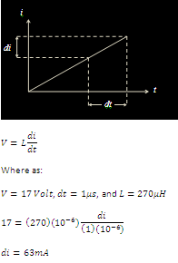
In theory, at 17V input, with 270uH, and 1us resolution of the 'onTime', I only can increase or decrease panel current by 63mA at a time (+/- 1W at 17V). Calculation as follow:


As stated in previous point, in practice, the input power does jump around +/- 1W at 17-ish panel voltage. Nice to see practice and theory agrees with each other.

Thursday, 17 April 2014

BMPPT Solar Charger (2)

Rightio, that peaking current that I previously reported? Well, that was me being un-educated that inductor in the 'fly-back mode' requires air-gap. Without the air-gap, my toroidal inductor was very quick went in to saturation and giving me much smaller inductance. I've found an excellent article here explaining it. Thanks to Dremmel, I simply cut air-gap cowboy style to my toroidal inductor.

That simple problem, paragraph above, took me literally hundreds of hours of troubleshooting, and couple of re-soldering activities due to burnt PCB tracks and components. Ouch...

But, I'm happy to report, by simply adding air-gap, now my BMPPT charger works properly. It actually works better than I anticipated (good problem to have). It tracks my solar panel very well up-to 25W output (during test day, it was very cloudy, couldn't test it all the way to the rated 80W). Efficiency during test also OK-ish (> 87%), even to include the Arduino board power consumption.

So, here it is the final schematic. Input capacitor (C1), and smooting capacitor (C3) were added after various tests:


Do note that exact component values are not critical. These components were selected because I was trying to re-use components that I already have. Final board photo, not looking that pretty:

Oh, the code for the Arduino Uno is here.

Charging current and final trickle voltage is all adjustable through software. The code linked above is to charge my 36V 11.6Ah lithium battery, i.e. charging stops at 42V. I didn't put current limit in the software.

Monday, 24 March 2014

BMPPT Solar Charger (1)

Update on my quest to design and build my own BMPPT electric bike lithium battery charger:
Searching what is out there in the first place:

  1. Genasun: Looks really good, but with USD300 price tag (due to custom voltage). Ouch, for stingy people like me;
  2. SPV1020, or complete with development board STEVAL-ISV009V1: Looks very promising, until I read the details that it only goes up to 40V. Not high enough for my e-Bike battery (I need 42V at the end of the charge);
  3. BMPPT 60 from GSL electronics: only good for 48V battery, not for my 36V battery.


So, the existing one in the market, either too expensive, or not suitable for my 36V battery. After researching into my options, I decided to go forward with Arduino Uno as the controller. Arduino Due would be definitely better (purely due to faster analog sampling time), but that's extra AUD70 that I don't want to spend. Besides, I already have the Uno in hand.

First thing, here's the simplified schematic of the boost controller. Nothing fancy:


What is not shown above is the voltage divider network and current sensing circuit to be fed to the Arduino Uno board. In the simulation above, you can see actual values. The pulse signal is mimicking the Uno Digital Output. The MOSFET symbol is incorrect, but hey, you get the idea. The inductor acts like the current source, and the switching circuit (by MOSFET) maintains the current by switching ON and OFF. Circuit above simulated using Falstad. I originally designed the system using following logic:


After doing the actual test, it's not looking good. It drew high peaking current with poor efficiency. After doing some investigation, I suspect the analog sampling is unreliable and causing my detection logic went hay-wire. So, I have no option but to go PWM mode. I am aware that SPV1020 also using PWM technique, but I'm struggling to get a good logic. Lots of trial and error at the moment. Will update...

Tuesday, 25 February 2014

Solar Charging for Electric Bike (2)

The cheap-skate version of my lithium battery solar charger was a success IF (there is a big IF) I monitor it continously, i.e. the output power of the converter (and losses) is less than the solar panel output power (Watt). I had to do this by changing the CC (Constant Current) setting.

The problem is, everytime the solar panel power (Watt) drops below the required output power (let say due to passing clouds), the DC-DC converter (CC-CV) becomes unstable. I'm guessing this is because the converter is trying to suck out even more current out of the panel. For example:

At 9 o'clock in the morning, I set the CC of the converter so that the output power of the solar panel reaches 39.4W (out of 80W rated Wp). When I tried to increase more power, the converter suddenly became unstable (making humming noise) and output of the solar panel drops to around 15 - 20W (jumping erratically). I had to decrease the CC setting all the way down in order to re-stablise the converter, and then turning it back up. unplugging and replugging the load didn't stabilise the converter.

Later, I found out that installing huge capacitor (I tried 15,000uF, definitely can do with less) at the converter input can help to stabilise the converter. Although, you still have to unplug the load and replug it back in.

So, in short, I was the slave labour to mimic the MPPT. By 12 mid-day, I managed to squeeze 67W out of the solar panel. The converter is pretty hot at this point of time (still touch-able) even with extra heatsink that I installed.

From my test, between 9am to 3pm (this time of day of the year), without any cloud, the panel can comfortably supply at least 40W (out of the specified 80Wp), so I don't need to fiddle much with the CC setting of the converter. Obviously, in practice, even the slightest cloud passing will throw this converter out of whack. So slave labour still required to monitor.

Oh, converter effeciency is around 89%, using power consumption figure from my in-line power meters. Not too far from the acclaimed 92% from the product website.

Next step, is to design and build my own BMPPT solar charger, as there is no way I can do this MPPT manually all the time. The current one in the market that fits my battery pack (36V 11.6Ah) simply doesn't exist. Either Genasun or GSL don't fit my charging profile. From googling the web, the Tim Nolan's one inspired me to make mine from Arduino Uno. Watch this space!

Wednesday, 5 February 2014

Solar Charging for Electric Bike

Thanks to absolute bargain I found from gumtree, now I can charge my electric bike battery using solar panel. Unfortunately, I can’t find any suitable charger system off-the-shelf. My requirement:

  1. MPPT (with booster) to charge e-bike battery directly from the solar panel. In my case, 12V solar panel to charge 36V lithium battery (Panasonic cells).
  2. Cost of the total system (solar panel plus chargers). If the whole system cost way too high ($/kWh of its lifetime), I’d rather charge them from the grid.


The closest one I got so far is http://genasun.com/all-products/solar-charge-controllers/for-lithium/gv-5-li-lithium-5a-solar-charge-controller/ but the price is a bit steep for me (must order the custom voltage for me). I'll put this on the back-burner when everything else fails :).

So, my idea #1 so far:

1. Solar Panel, 12V 80W (it only cost me AUD110!!);
2. DC-DC converter, CVCC (constant voltage constant current) (Ref #1 below);
3. Ah and Wh meter (Ref #2 below);
4. eBike battery (mine is 36V 11.6Ah with Panasonic cells)

Reasoning behind my selection:

  1. There is no MPPT in the DC-DC converter above. However, considering the cheap as chips unit, and plenty of 'oomph' in my solar panel, me think this should be OK.
  2. It's not a dedicated lithium charger. Although I can set the CV (Constant Voltage) to 42V, I'm not sure what is the degrading effect of leaving 'trickle' (float) charge at 42V. Reading many articles regarding 'float' charge of lithium batteries, I've come to conclusion "simply don't do it". Although, from my experience with the supplied charger, once it's topped up to 42V, it stays in this state for a long time. When I left the battery unused (after full top-up) for almost 2 days, the voltage is still 41-ish volt.
  3. Due to unknown risk above, I've decided to use the Ah (complete with Wh) meter. So I can monitor the charging accurately.


My idea #2 is to buy el-cheapo 12V to 240V inverter and use my supplied charger. However, I like the idea setting the charging current of idea #1 :).

Cost so far:


Not too bad. Definitely comparable to my grid-connected charger. Figures maybe optimistic (as in, the ability to charge everyday) :).

Results? Well, I need to wait until I get the converter first!

References:
1. http://www.prodctodc.com/dc-10835v-to-3563v-boost-converter-constant-current-led-driver-power-module-p-152.html#.Uum4Dz2Sx8E
2. http://www.ebay.com.au/itm/150Amp-Watt-Meter-Power-Analyser-Digital-LCD-/291054073099?pt=AU_Toys_Hobbies_Radio_Controlled_Vehicles&hash=item43c42cb50b&_uhb=1