Wednesday, 15 April 2015

Menuju Rumah Mandiri Energi: Pendahuluan

“Saya memakai beberapa lampu dan kipas angin, butuh berapa panel surya supaya rumah saya tidak perlu PLN lagi?”

“Saya sudah muak PLN byar-byar-pret melulu. Panel surya bisa mengatasi masalah ini nggak?”

“Kalau gubuk aja udah pake panel surya, kenapa kita tidak bisa?”


Sepertinya komentar-komentar seperti ini sudah tidak asing lagi belakangan ini. Nah, tujuan artikel ini adalah untuk menjelaskan secara terinci, apa yang dibutuhkan untuk mandiri dalam hal kelistrikan, alias, tidak perlu PLN (Off-Grid). Sebelum terjun ke ‘Off-Grid’, perlu diketahui ada juga yang namanya ‘On-Grid’. Untuk perbandingan on-grid dengan off-grid, ini merupakan topik tersendiri: klik disini.

Andai saja jawabannya sederhana, “Beli aja UPS (uninterruptible Power Supply), terus colok listrik rumah ke situ. Gampang toh?”. Kalo rumah situ gubuk, ya ini jawaban yang benar. Tapi, kalau rumah situ lebih besar dari gubuk, untuk mengandalkan seluruh rumah berdasarkan tenaga surya, ini lebih rumit.

Sebelum menjelaskan lebih lanjut, saya akan jelaskan ‘melistriki’ rumah, dengan analogi ‘mengairi’ rumah:

Dalam ‘mengairi’ rumah modern, air disalurkan ke seluruh rumah melalui pipa-pipa. Nah, biasanya, tekanan air dari PAM (Perusahaan Air Minum) sangat rendah, sehingga tidak bisa langsung digunakan.

Solusinya, air dari PAM ditampung di bak besar, lalu dipompa ke seluruh rumah. Alternatifnya, air dari PAM ditampung di bak yang berada di ketinggian, lalu disalurkan ke seluruh rumah melalui gravitasi. Ilustrasi sebagai berikut:


Nah, melalui ilustrasi di atas, kita bisa tahu beberapa hal berikut:
  • Berapa banyak air yang dibutuhkan oleh semua penghuni rumah? Dalam sehari? Seminggu?
  • Berapa banyak air yang harus di-supply oleh PAM?
  • Berapa besar bak air yang harus digunakan?


Dari analogi di atas, pertanyaan ‘berapa banyak panel surya dan baterai yang saya perlukan?’ bisa dijawab dengan menggunakan analogi bak air di atas:
  • Berapa banyak listrik yang saya konsumsi? Sehari? Seminggu?
  • Berapa banyak listrik yang butuh di-supply? (Alias, berapa banyak panel surya yang saya butuhkan)
  • Berapa banyak baterai yang saya butuhkan?
Nah, dalam tulisan selanjutnya, akan saya bahas lebih lanjut.

Thursday, 12 June 2014

BMPPT Solar Charger (3)

In pursuit improving my Boost MPPT charger, I have done the following:


  1. Update the software to use in-built PWM functionality of Arduino Uno. I've found out increasing frequency of the PWM is easy-as (simply add a line of code!!). The converter is now no longer making audible noise. Also, I get back most of the computing power of the Uno, instead of fully dedicated PWM routine. The negative of increasing PWM frequency is reduced efficiency. In my case, running 31kHz has reduced efficiency by 1%!
  2. Use MOSFET gate driver: this has increased efficiency by 2 - 3%, not bad! My inexperience made me choosing MOSFET gate driver without under-voltage lock-out, which caused the converter unstable during start-up. After much troubleshooting, I've found out the MOSFET gate driver locks the MOSFET to ON position during low voltage start-up, which cause the whole circuit short-circuited. This is now rectified by choosing another driver with under-voltage lock-out;
  3. Inductor: I've wound my own inductor using proper gapped core ETD34 core with much thicker copper wire. This has increased the current capacity and reduced EMI (so they said). However, no increased efficiency whatsoever compared to my old cowboy inductor.


I'm a bit disappointed that I haven't managed increased the efficiency significantly. I suspect my measurement method is inaccurate. As I simply read the watt reading from the el-cheapo watt-meter at the input. As the current is rippling, actual watt figure is probably different. So, next time I need to measure it properly using oscilloscope. None of the component is hot this time, so surely it's better than 90%.

New Schematic:


New software, click here. Note that the software includes my customised voltage selection during start-up. This is to accomodate my lead-acid 24V battery charging for the UPS. Yup, that's right, my shed is now off-grid too!

Thursday, 8 May 2014

Arduino Uno Shield Boost MPPT Cost

So, how much it cost exactly my home-made Arduino Uno shield for Boost MPPT charger? Have I reached my original goal to create the el-cheapo version of Genasun boost MPPT lithium charger?

If I didn't account for:

  • Hundreds of hours spending time in this project (I'm a slow learner),
  • Buying an awesome picoscope USB oscilloscope (to find out what was wrong with my boost converter due to my lack of knowledge),
  • PCB making infrastructure (solder, etching, etc etc).


Then the answer is absolutely yes! So far, components only cost me AUD65.80. If I were to get Genasun, that would cost me USD300!! Yes yes, it would financially much more beneficial if I were to buy the Genasun in the first place and not spending hundreds of hours and testing equipment... but... I learnt a lot from this project.

Breakdown of component cost as follow:


Total minimum purchase cost is shown above, as the minimum retail quantity was not one. I purchased them all from RS components.

There are components not shown in the cost table above (i.e. resistors and some diodes) because I've used my left-over components from my previous adventure. I ended up buying new Arduino Uno board, because I've blown up my original Uno freebie due to my own stupid mistake (literally, there was smoke coming out from the board after a 'POP'). So stupid, I won't share.

I can't share my board layout as it's riddled with problem, i.e. power jack is sitting on top of the USB connector, and the current sensing pad size is slightly wrong. I 'designed' the board using Microsoft Word, how silly is that?

Too bad, no one (that I can find in Google) has made buck/boost Arduino shield, nor boost only version that I can buy. So, until then, I'll be still using mine in the near future. 

Tuesday, 6 May 2014

Boost MPPT Charger Details (1)

So, meanwhile fresh in my mind, I'd better document how the software works. Following flow chart is the simplified version of my Boost MPPT charger Arduino Uno code:


Would I code this differently? Of course! But, the code as-is, works well. It has been tested with me trying to break it to find bugs. After various testing, this code has been fine tuned. For example, 5000 cycle times for the PWM. Too little, causing the MPPT tracking stuck in lower power, no idea why. Too large, not good for the speed of MPPT tracking. Plugging in and out battery meanwhile the sun is full shining was also tested (to make sure the code handles overvoltage, etc etc).

If I have more time, I would code using Arduino PWM in-built feature next time. I've just found out (after all of this), that I can change the PWM frequency. Heck, the more I spend time on this project, the more things I find can be improved.

What testings did I do? In brief:

Accuracy of MPPT tracking:
Very well, thank you very much. I did this by temporarily breaking the connection and reconnect the solar panel with another DC-DC converter. I noted down the power consumption of the input in-line power meter, immediately prior the converter becomes unstable, and compare this against my Arduino-Uno Boost MPPT charger input power consumption. Very close indeed. I should be honest, the test wasn't very scientific, as I only tested 2 points, i.e. at 30W and at 55W.

Efficiency of the charger:
as noted before, at least 87%. But, this is only true for power consumption above 17-ish Watt. Below this, the efficiency drops significantly (due to various reasons beyond the scope of today's blog :) ). At 3W, it's only 40% efficient. Note though, I need to repeat this efficiency test to get more accurate results. As the input power figure does jump around +/-1W due to the Perturb and Observe algorithm. I need to slow down the MPPT tracking to get the efficiency figure correctly. Why jumping around that much? Well, see next point.

Resolution of the MPPT tracking:
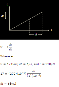
In theory, at 17V input, with 270uH, and 1us resolution of the 'onTime', I only can increase or decrease panel current by 63mA at a time (+/- 1W at 17V). Calculation as follow:


As stated in previous point, in practice, the input power does jump around +/- 1W at 17-ish panel voltage. Nice to see practice and theory agrees with each other.

Thursday, 1 May 2014

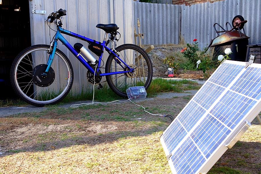
Mengisi Batere Sepeda Listrik dengan Tenaga Surya

Setelah tes lebih lanjut, sepeda listrik sang penulis sekarang bisa langsung di-isi dari panel surya, dengan rangkaian penjejak titik daya maksimum (atau MPPT ingglisnya). Spesifikasi:

Panel surya: 12V 80W (20.7V tegangan tanpa beban)
Pengisi batere: bikinan sang penulis sendiri (lihat artikel sebelumnya)
Batere sepeda: 36V 11.6Ah Lithium (NMC dari Panasonic)
Sepeda listrik: Hasil konversi.

Dengan rangkaian penjejak titik daya maksimum, sang penulis sekarang bisa lega karena tenaga panel surya diperes semaksimal mungkin. Sayang dong, kalau tenaga listrik yang dihasilkan tak terpakai secara maksimum?

Alhasil:


Rangkaian pengisi batere bisa menaikkan tegangan panel surya yang lebih rendah dibanding tegangan beban (batere).

Setelah coba-coba, ternyata kalau panel surya diposisikan ke arah matahari, bedanya lumayan banyak. Contoh, jam 9 pagi, surya panel diposisikan menghadap langsung ke matahari, dayanya naik ke sekitar 60 Watt, dibanding 35 Watt kalau menghadap ke atas (posisi matahari siang bolong). Ya, masalahnya, siapa yang sempet merubah panel surya seharian?

Thursday, 17 April 2014

Rangkaian Penjejak Titik Daya Maksimum

Rangkaian berikut dipakai untuk nge-boost voltase panel surya, lalu digunakan untuk mengisi baterai. Contoh, menggunakan surya panel 12V untuk mengisi baterai 36V yang biasa digunakan untuk sepeda listrik:

Arduino Uno digunakan untuk mengendalikan rangkaian di atas. Kodenya dapat ditemukan di sini.

Rangkaian di atas sudah di-tes di lapangan dan dapat menjejak panel surya sampai 25Watt. Seharusnya dapat digunakan sampai 75W (panel surya 12V), tapi belum di-tes berhubung awan tebal ketika tes :) . Efisiensi lebih dari 87%.

Berhubung semuanya dikontrol oleh Arduino, rangkaian di atas bisa jadi super fleksibel. Contoh, ketika batere sudah penuh, kode yang di link di atas secara otomatis menghentikan pegisian batere, ke mode 'trickle charge'.

BMPPT Solar Charger (2)

Rightio, that peaking current that I previously reported? Well, that was me being un-educated that inductor in the 'fly-back mode' requires air-gap. Without the air-gap, my toroidal inductor was very quick went in to saturation and giving me much smaller inductance. I've found an excellent article here explaining it. Thanks to Dremmel, I simply cut air-gap cowboy style to my toroidal inductor.

That simple problem, paragraph above, took me literally hundreds of hours of troubleshooting, and couple of re-soldering activities due to burnt PCB tracks and components. Ouch...

But, I'm happy to report, by simply adding air-gap, now my BMPPT charger works properly. It actually works better than I anticipated (good problem to have). It tracks my solar panel very well up-to 25W output (during test day, it was very cloudy, couldn't test it all the way to the rated 80W). Efficiency during test also OK-ish (> 87%), even to include the Arduino board power consumption.

So, here it is the final schematic. Input capacitor (C1), and smooting capacitor (C3) were added after various tests:


Do note that exact component values are not critical. These components were selected because I was trying to re-use components that I already have. Final board photo, not looking that pretty:

Oh, the code for the Arduino Uno is here.

Charging current and final trickle voltage is all adjustable through software. The code linked above is to charge my 36V 11.6Ah lithium battery, i.e. charging stops at 42V. I didn't put current limit in the software.