In pursuit improving my Boost MPPT charger, I have done the following:
I'm a bit disappointed that I haven't managed increased the efficiency significantly. I suspect my measurement method is inaccurate. As I simply read the watt reading from the el-cheapo watt-meter at the input. As the current is rippling, actual watt figure is probably different. So, next time I need to measure it properly using oscilloscope. None of the component is hot this time, so surely it's better than 90%.
New Schematic:

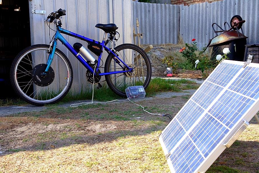
New software, click here. Note that the software includes my customised voltage selection during start-up. This is to accomodate my lead-acid 24V battery charging for the UPS. Yup, that's right, my shed is now off-grid too!
- Update the software to use in-built PWM functionality of Arduino Uno. I've found out increasing frequency of the PWM is easy-as (simply add a line of code!!). The converter is now no longer making audible noise. Also, I get back most of the computing power of the Uno, instead of fully dedicated PWM routine. The negative of increasing PWM frequency is reduced efficiency. In my case, running 31kHz has reduced efficiency by 1%!
- Use MOSFET gate driver: this has increased efficiency by 2 - 3%, not bad! My inexperience made me choosing MOSFET gate driver without under-voltage lock-out, which caused the converter unstable during start-up. After much troubleshooting, I've found out the MOSFET gate driver locks the MOSFET to ON position during low voltage start-up, which cause the whole circuit short-circuited. This is now rectified by choosing another driver with under-voltage lock-out;
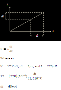
- Inductor: I've wound my own inductor using proper gapped core ETD34 core with much thicker copper wire. This has increased the current capacity and reduced EMI (so they said). However, no increased efficiency whatsoever compared to my old cowboy inductor.
I'm a bit disappointed that I haven't managed increased the efficiency significantly. I suspect my measurement method is inaccurate. As I simply read the watt reading from the el-cheapo watt-meter at the input. As the current is rippling, actual watt figure is probably different. So, next time I need to measure it properly using oscilloscope. None of the component is hot this time, so surely it's better than 90%.
New Schematic:
New software, click here. Note that the software includes my customised voltage selection during start-up. This is to accomodate my lead-acid 24V battery charging for the UPS. Yup, that's right, my shed is now off-grid too!