Tuesday, 6 May 2014

Boost MPPT Charger Details (1)

So, meanwhile fresh in my mind, I'd better document how the software works. Following flow chart is the simplified version of my Boost MPPT charger Arduino Uno code:


Would I code this differently? Of course! But, the code as-is, works well. It has been tested with me trying to break it to find bugs. After various testing, this code has been fine tuned. For example, 5000 cycle times for the PWM. Too little, causing the MPPT tracking stuck in lower power, no idea why. Too large, not good for the speed of MPPT tracking. Plugging in and out battery meanwhile the sun is full shining was also tested (to make sure the code handles overvoltage, etc etc).

If I have more time, I would code using Arduino PWM in-built feature next time. I've just found out (after all of this), that I can change the PWM frequency. Heck, the more I spend time on this project, the more things I find can be improved.

What testings did I do? In brief:

Accuracy of MPPT tracking:
Very well, thank you very much. I did this by temporarily breaking the connection and reconnect the solar panel with another DC-DC converter. I noted down the power consumption of the input in-line power meter, immediately prior the converter becomes unstable, and compare this against my Arduino-Uno Boost MPPT charger input power consumption. Very close indeed. I should be honest, the test wasn't very scientific, as I only tested 2 points, i.e. at 30W and at 55W.

Efficiency of the charger:
as noted before, at least 87%. But, this is only true for power consumption above 17-ish Watt. Below this, the efficiency drops significantly (due to various reasons beyond the scope of today's blog :) ). At 3W, it's only 40% efficient. Note though, I need to repeat this efficiency test to get more accurate results. As the input power figure does jump around +/-1W due to the Perturb and Observe algorithm. I need to slow down the MPPT tracking to get the efficiency figure correctly. Why jumping around that much? Well, see next point.

Resolution of the MPPT tracking:
In theory, at 17V input, with 270uH, and 1us resolution of the 'onTime', I only can increase or decrease panel current by 63mA at a time (+/- 1W at 17V). Calculation as follow:
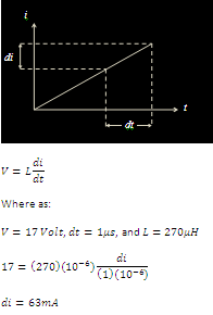

As stated in previous point, in practice, the input power does jump around +/- 1W at 17-ish panel voltage. Nice to see practice and theory agrees with each other.

Thursday, 1 May 2014

Mengisi Batere Sepeda Listrik dengan Tenaga Surya

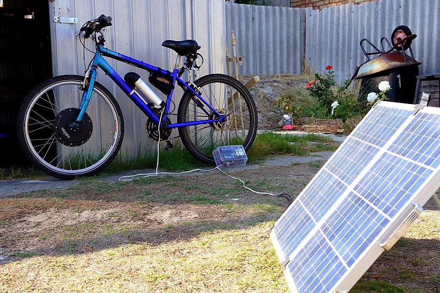
Setelah tes lebih lanjut, sepeda listrik sang penulis sekarang bisa langsung di-isi dari panel surya, dengan rangkaian penjejak titik daya maksimum (atau MPPT ingglisnya). Spesifikasi:

Panel surya: 12V 80W (20.7V tegangan tanpa beban)
Pengisi batere: bikinan sang penulis sendiri (lihat artikel sebelumnya)
Batere sepeda: 36V 11.6Ah Lithium (NMC dari Panasonic)
Sepeda listrik: Hasil konversi.

Dengan rangkaian penjejak titik daya maksimum, sang penulis sekarang bisa lega karena tenaga panel surya diperes semaksimal mungkin. Sayang dong, kalau tenaga listrik yang dihasilkan tak terpakai secara maksimum?

Alhasil:


Rangkaian pengisi batere bisa menaikkan tegangan panel surya yang lebih rendah dibanding tegangan beban (batere).

Setelah coba-coba, ternyata kalau panel surya diposisikan ke arah matahari, bedanya lumayan banyak. Contoh, jam 9 pagi, surya panel diposisikan menghadap langsung ke matahari, dayanya naik ke sekitar 60 Watt, dibanding 35 Watt kalau menghadap ke atas (posisi matahari siang bolong). Ya, masalahnya, siapa yang sempet merubah panel surya seharian?

Thursday, 17 April 2014

Rangkaian Penjejak Titik Daya Maksimum

Rangkaian berikut dipakai untuk nge-boost voltase panel surya, lalu digunakan untuk mengisi baterai. Contoh, menggunakan surya panel 12V untuk mengisi baterai 36V yang biasa digunakan untuk sepeda listrik:

Arduino Uno digunakan untuk mengendalikan rangkaian di atas. Kodenya dapat ditemukan di sini.

Rangkaian di atas sudah di-tes di lapangan dan dapat menjejak panel surya sampai 25Watt. Seharusnya dapat digunakan sampai 75W (panel surya 12V), tapi belum di-tes berhubung awan tebal ketika tes :) . Efisiensi lebih dari 87%.

Berhubung semuanya dikontrol oleh Arduino, rangkaian di atas bisa jadi super fleksibel. Contoh, ketika batere sudah penuh, kode yang di link di atas secara otomatis menghentikan pegisian batere, ke mode 'trickle charge'.

BMPPT Solar Charger (2)

Rightio, that peaking current that I previously reported? Well, that was me being un-educated that inductor in the 'fly-back mode' requires air-gap. Without the air-gap, my toroidal inductor was very quick went in to saturation and giving me much smaller inductance. I've found an excellent article here explaining it. Thanks to Dremmel, I simply cut air-gap cowboy style to my toroidal inductor.

That simple problem, paragraph above, took me literally hundreds of hours of troubleshooting, and couple of re-soldering activities due to burnt PCB tracks and components. Ouch...

But, I'm happy to report, by simply adding air-gap, now my BMPPT charger works properly. It actually works better than I anticipated (good problem to have). It tracks my solar panel very well up-to 25W output (during test day, it was very cloudy, couldn't test it all the way to the rated 80W). Efficiency during test also OK-ish (> 87%), even to include the Arduino board power consumption.

So, here it is the final schematic. Input capacitor (C1), and smooting capacitor (C3) were added after various tests:


Do note that exact component values are not critical. These components were selected because I was trying to re-use components that I already have. Final board photo, not looking that pretty:

Oh, the code for the Arduino Uno is here.

Charging current and final trickle voltage is all adjustable through software. The code linked above is to charge my 36V 11.6Ah lithium battery, i.e. charging stops at 42V. I didn't put current limit in the software.

Monday, 24 March 2014

BMPPT Solar Charger (1)

Update on my quest to design and build my own BMPPT electric bike lithium battery charger:
Searching what is out there in the first place:

  1. Genasun: Looks really good, but with USD300 price tag (due to custom voltage). Ouch, for stingy people like me;
  2. SPV1020, or complete with development board STEVAL-ISV009V1: Looks very promising, until I read the details that it only goes up to 40V. Not high enough for my e-Bike battery (I need 42V at the end of the charge);
  3. BMPPT 60 from GSL electronics: only good for 48V battery, not for my 36V battery.


So, the existing one in the market, either too expensive, or not suitable for my 36V battery. After researching into my options, I decided to go forward with Arduino Uno as the controller. Arduino Due would be definitely better (purely due to faster analog sampling time), but that's extra AUD70 that I don't want to spend. Besides, I already have the Uno in hand.

First thing, here's the simplified schematic of the boost controller. Nothing fancy:


What is not shown above is the voltage divider network and current sensing circuit to be fed to the Arduino Uno board. In the simulation above, you can see actual values. The pulse signal is mimicking the Uno Digital Output. The MOSFET symbol is incorrect, but hey, you get the idea. The inductor acts like the current source, and the switching circuit (by MOSFET) maintains the current by switching ON and OFF. Circuit above simulated using Falstad. I originally designed the system using following logic:


After doing the actual test, it's not looking good. It drew high peaking current with poor efficiency. After doing some investigation, I suspect the analog sampling is unreliable and causing my detection logic went hay-wire. So, I have no option but to go PWM mode. I am aware that SPV1020 also using PWM technique, but I'm struggling to get a good logic. Lots of trial and error at the moment. Will update...

Tuesday, 25 February 2014

Solar Charging for Electric Bike (2)

The cheap-skate version of my lithium battery solar charger was a success IF (there is a big IF) I monitor it continously, i.e. the output power of the converter (and losses) is less than the solar panel output power (Watt). I had to do this by changing the CC (Constant Current) setting.

The problem is, everytime the solar panel power (Watt) drops below the required output power (let say due to passing clouds), the DC-DC converter (CC-CV) becomes unstable. I'm guessing this is because the converter is trying to suck out even more current out of the panel. For example:

At 9 o'clock in the morning, I set the CC of the converter so that the output power of the solar panel reaches 39.4W (out of 80W rated Wp). When I tried to increase more power, the converter suddenly became unstable (making humming noise) and output of the solar panel drops to around 15 - 20W (jumping erratically). I had to decrease the CC setting all the way down in order to re-stablise the converter, and then turning it back up. unplugging and replugging the load didn't stabilise the converter.

Later, I found out that installing huge capacitor (I tried 15,000uF, definitely can do with less) at the converter input can help to stabilise the converter. Although, you still have to unplug the load and replug it back in.

So, in short, I was the slave labour to mimic the MPPT. By 12 mid-day, I managed to squeeze 67W out of the solar panel. The converter is pretty hot at this point of time (still touch-able) even with extra heatsink that I installed.

From my test, between 9am to 3pm (this time of day of the year), without any cloud, the panel can comfortably supply at least 40W (out of the specified 80Wp), so I don't need to fiddle much with the CC setting of the converter. Obviously, in practice, even the slightest cloud passing will throw this converter out of whack. So slave labour still required to monitor.

Oh, converter effeciency is around 89%, using power consumption figure from my in-line power meters. Not too far from the acclaimed 92% from the product website.

Next step, is to design and build my own BMPPT solar charger, as there is no way I can do this MPPT manually all the time. The current one in the market that fits my battery pack (36V 11.6Ah) simply doesn't exist. Either Genasun or GSL don't fit my charging profile. From googling the web, the Tim Nolan's one inspired me to make mine from Arduino Uno. Watch this space!

Ah VS Wh for Lithium Battery State of Charge

Following previous post, I've found out the in-line power meter that I bought from eBay does not count Ah and Wh properly. This one only counts properly when output current and power is constant. When the output drops to zero, the Ah and Wh also drops to zero. What the??

So, I managed to find this one from Altronics (Manson), and work as expected. Definitely not worth to buy el-cheapo in-line power meter, for any model (after googling around). Save yourself lots of trouble and get the manson one instead. So, here's my final circuit:


Trying to minimise my loss, I use the crap-o-meter to display Volt, Ampere, and Watt for solar panel output. The good one, I use for coulomb-counting for battery charging. I wasn't sure whether to use Ah or Wh to calculate the State of Charge of my Lithium battery pack. My original thought was using Wh, as surely energy is better indicator? However, I trust white paper more than some Joe-Blog opinion (like myself). ALL white paper that I found so far, mention 'Coulomb counting' (i.e. counting Ah) is one way to monitor your state of charge, so that what I'll do for my battery pack. One of example of the white paper can be found here.

From my own testing, charging using Ah seems more accurate than using the Wh. Here is the example:

I used 6.864Ah or 248.02Wh in one of my commuting day last week. I got this figure from my 'cycle analyst' installed in my electric bike.

When charging (with constant current 1.2A most of the time), I stopped the charging at 6.6Ah or 259.6Wh according to my Manson in-line power meter (using my solar charging circuit). At this time, the voltage of the battery pack was 41.78V. After almost 2-day rest of the battery, my battery pack voltage was 41.4V (using cycle analyst).

Hence, from the above, definitely use Ah, NOT Wh counting for reliable discharge and charging of your lithium battery pack.

As you may already know, most lithium battery pack specify both in Ah and Wh. For example, my battery pack says 36V, 11.6Ah, 416Wh. However, from my usage so far, there is a few Watt discrepancy between the actual Wh and Ah (by simply multiplying it with 36). So, again, using Ah, not Wh for battery State of Charge, is definitely more accurate.